- Apc Rj45 Serial Cable Pinout Diagram
- | UPS Management Devices & PowerChute Software
- Apc Rj45 Serial Cable Pinout Box

Apc Rj45 Serial Cable Pinout Diagram
- Jan 11, 2019 I need the pinout for an APC serial cable. The pinout is different to a Cisco console cable, I believe some of the pins on the RJ-45 (UPS) end are shorted together. This is the cable I need to re-create temporarily so I can update the damn firmware.
- Serial port: Access internal menus by connecting this port (RJ-11 modular port) to a serial port on your computer, using the supplied serial cable (APC part number 940-0144). The cable 940-0144 on amazon would cost me 95$ with shipping and tax. There is one on ebay a bit cheaper.
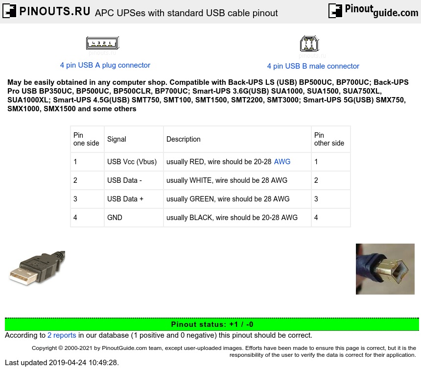
APC USB cable schematic Cable Pinout - Pinout search.Quick and easy to find any pinout diagrams and related information for various types of connectors and cables APC USB cable schematic Cable Pinout - Pinout cable and connector diagrams-usb, serial rs232,rj45 ethernet, vga, parallel, atx, dvi. APC USB cable schematic. Connector or cable wiring APC part# 940-0127B. 10 pin RJ50 (10P10C) male connector to the APC cable. 4 pin USB A or USB B plug connector to the PC.
Should be compatible with:
- Back-UPS Pro BP650, BP650S, BP650SC, BP420, BP420S, BP420SC, BP280S (also compatible with 940-0095B cable)
- Smart-UPS 3G SU420NET, SU620NET, SU700NET, SU1000NET, SU1400NET, SU2200NET, SU3000NET, SU2200XLNET, SU2200XLTNET, SU3000TNET, SU5000T, SU1400RMXL3U, SU2200RM3U, SU2200RMXL3U, SU2200RMXLNET, SU2200RMXLTNET, SU3000RM3U, SU3000RMNET, SU3000RMT3U, SU3000RMXL3U, SU5000, SU5000RMT5U
- Smart-UPS 3.5G SU700RM2U, SU1000RM2U, SU1400RM2U
- Smart-UPS 3.6G(Serial) SUA1000, SUA1500, SUA750XL, SUA1000XL
- Smart-UPS 4.0G(Serial) SUA2200, SUA2200RM2U, SUA3000, SUA3000RM2U, SUA3000RMT2U
- Smart-UPS SC SC420, SC620
- Matrix MX3000, MX5000, MX3000XR, MX5000XR
APC Part# 940-0024A, 940-0024B, 940-0024C, 940-0024D, 940-1524 cable scheme
| UPS Management Devices & PowerChute Software
According to APC forum, letter suffix is related to (change of?) manufacturer or revision, not wiring, and cables are electrically interchangable.
'Simple scheme' diagram further below looks correct for 940-0024 & A,B,C or D revisions and 940-1524 which is 15' long cable; and matches what viewed on a third-party site.
Simple scheme (APC 940-1524D cable)
| UPS Signal Name | DB-9 Male (UPS end) | DB-9 Female (PC end) | PC Signal Name |
| TX / AC Fail | 2 | 2 | Rx, Received Data |
| RX / Shutdown | 1 | 3 | Tx, Transmitted Data |
| Common | 9 | 5 | GND |
At the PC end: pins 1,4 (DCD, DTR) shorted; pins 7,8 (RTS, CTS) shorted.
DB-9 shells are also connected.
The 9,1,2 pins look OK for the basic mode, but the smart mode seems to need extra components.
4+9=GND
8=25V
7=5V

Alternative scheme. Smart UPS Console Cable APC part # is unknown.
DB 9 PC Male | UPS DB 9 Female | Comment |
1 & 2 | 2 | RX?? Short Pins 1 & 2 on PC side connect to Pin 2 on UPS side |
3 | 1 | TX ?? |
4 | N/C | No Connection |
5 | 9 | GND |
6 | N/C | No Connection |
7 & 8 | N/C | Short Pin 7 & 8 on PC side. |
Terminal Set Up:
Apc Rj45 Serial Cable Pinout Box

2400 baud 8 bit no parity 1 stop no handshake.
Apply the port settings to establish the connection.
Press 3-5 times to display the username prompt.
The default SmartUPS username is apc and default password is apc